|
Updates
2010 September 14 update: Packard engine data added.
2010 March 1 update: Added camber information, and fuel tank capacity corrected.
The following specifications were derived from Elco drawings, the Navy build manual, reference books, and the net. Please let me know if you find an error or can supply more detailed information. Note that the Navy build manual is a later version of the 103 class manual, for PT 565-624, and that there could be numeric typos from the character recognition program used for converting the manual to the web.
For simplicity I use keel for both the keel and stem post. Technically the stem post ends at frame 9 and the keel begins. Depth measurements are from the plans horizontal base line which is slightly below the lowest part of the planked hull. The base line is parallel to the water line. Measurements along the keel are given in both frame locations and stations. More about frames and stations can be found on the Hull component page.
|
Specifications, 1942 Elco 80' Patrol Torpedo (PT) Boat
|
Elco Naval Division of the Electric Boat Company, Bayonne, New Jersey
|
Per the Navy build manual:
Length overall, extreme: 80' 3" (963")
Per Elco drawings:
80' (960") to outside of planking from forward point to the aftermost point (with the transom angle, deck centerline would be an additional .5"). Rear guard at the transom extended out an additional 6".
942" to the end of the keel.
|
|
20' - 7" (247") beam over planking.
20' - 10 3/4" (250.75") extreme beam at outside of guard.
Max beam located at frame 24, 347" aft of the forward point, according to Elco Frame Offsets plan number 3005.
|
|
73' 4" (880").
This is measured at the designed water line, or where the water will be with the designed load on the boat.
It is located between station 0 (68") to station 10 (948"). Stations are 88" length divisions along the LWL and are used on the lines plan for cross-sectional lines. See the Hull page for details.
|
Halfway along the LWL, placing it 508" back from the forward point.
|
|
8' 9 1/2" (105.5") measured amidships.
This measurement can be confusing since it is measured from the bottom of the keel (minus the planking) to the deck sheer line.
|
Max planked keel depth is 5.25" above the base line and located at frame 25, 359" aft of the forward point, according to Elco plan 3005, Frame Offsets.
|
|
These are the curvature of surfaces. For example, using the deck sheer specs, when the beam of the hull is 21' the sheer (outer edge of deck) will be 4.5" lower than the deck centerline. With surfaces that have curved sides like the deck sheer this results in differing heights between the deck centerline and the deck sheer line as the beam changes.
Deck sheer: 4.5" in 21' according to Elco drawing 3086, Type Sections, and Deck Framing drawings. The sheer varied slightly to match the designed sheer line. Radius = 1766.25".
Chart house roof: 3.5" in 8' 3" according to Elco drawing 3231, Construction Of Bridge And Chart Room Trunk. Radius = 351.786".
Day room roof: 3.5" in 8' 3" according to Elco drawing 3230, Construction Of Cabin Trunk. Radius = 351.786".
Engine hatch: 2" in 8' according to Elco drawing 3086, Type Sections. Radius = 577".
Deck hatch: 0.25" in 23.5" according to Elco drawing 3470 20" X 24" Hatch Frame And Cover. The crown runs fore to aft. Radius = 276.25".
The formula to derive a radius from the width and height of a camber is:
radius = (height/2) + ((width * width) / (8 * height))
Where height equals the camber and width equals the given "in" dimension. For those not having math as a second language, the order of the operations, indicated by the "( )", is important. Do the inner ones first like so:
1. Divide the height by 2.
2. Multiply the width by the width.
3. Multiply 8 by the height.
4. Divide the result from step 2 by the result from step 3.
5. Add the result from step 1 to the result from step 4 to get the radius.
|
 Measured from the draft clearance line at frame 69. This angled line is drawn from the center prop low point, to the point where it would angle up to touch the hull a bit aft of the bow. It ends up being about 20" below the base line at frame 69.
Per the Navy build manual:
SECTION A-1, GENERAL, Principal dimensions. The following data are for information only:
Draft, normal, under 28" propellers: 5' 3/4"
Per other references, drawings and books:
5' - 3", 5' - 6" 1945
|
51 tons, 61 tons 1945 version
|
43 kts, 41 kts 1945 version
|
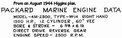 3 engines, supercharged Packard V12 model 4M-2500. Based on the Packard 3A-2500 aircraft engine.
Outboard engines were reversed with V drives, some later boats may have had outboard engines spaced farther apart facing the same way as the center engine.
From a Packard Engine 4M-2500 Manual, Specifications and Performance


|
 Manufacturer: Federal Mogul Equi-Poise.
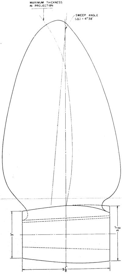
The following pitch and diameter information is based on PT historian Andy Small's research. His research shows that Elco 80' boats were equipped with 28" diameter propellers until PT 613 (direct drive boats) which used 29" diameter propellers. Pitch = inches traveled per revolution (with no slip) and relates to the blades angle to the hub.
Center: 28" diameter x 28 pitch, right hand.
Outboard: 28" diameter x 29" pitch, right hand.
Per Feb 2, 1943 BUSHIPS PT-103 Class Propeller drawing 78095:
Diameter: 28".
Pitch: 28".
Weight: 61 pounds.
Material: bronze casting to material specification Federalite-55.
Hub: 5.5" length, 3.5" front diameter, 3" rear diameter.
Per the Navy build manual:
There shall be 3 aluminum-manganese-bronze right hand turning propellers per vessel. The diameter of the propellers shall not exceed 30 inches. Hub length will not exceed 8 1/2 inches.
SECTION A-1, GENERAL, Principal dimensions. The following data are for information only:
Draft, normal, under 28" propellers: 5' 3/4"
SECTION S8, TRIAL REQUIREMENTS:
(a) Propeller test. This test shall be conducted in accordance with instructions issued by the Bureau of Ships for the type boat of each boatbuilder for the purpose of selecting the proper propeller for service conditions. Such a test shall be repeated as conditions of loading or design changes require.
|
 3000 gallons of aviation gasoline in 3 tanks. The center tank holds 1300 gallons and the wing tanks 850 gallons each. The day room has a removable roof for tank access.
|
259 miles at 35 knots.
|
|
Maximum cruising at 2,000 rpm.
Slow cruising at 1,200 rpm.
Minimum cruising at 800 rpm.
Idle at 600 rpm.
|
Max 3,000rpm, 40+ knots
|
11, 2 officers and 9 enlisted men, 1945: 17, 3 officers and 14 enlisted men.
|
 About 200 gallons. The chart house roof has a removable section, and the chart room a removable floor, for tank access.
|
|

