|
Updates
2015 December 10 update: Some information on hull fittings added. Thanks to Daniele Klay for sending the results of his bailer research!
2010 April 10 update: Deck construction table added.
2010 February 7 update: Deck beam dimension table to Elco drawings added.
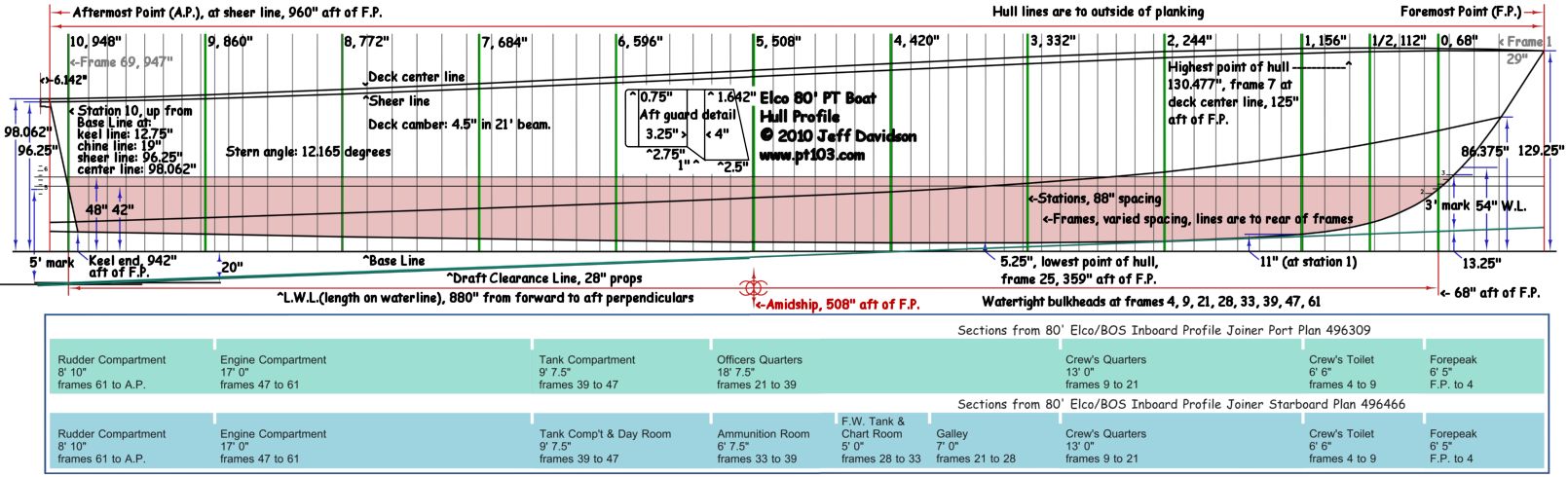
2010 January 11 update: Hull profile drawing updated to Elco drawings.
The following information is based mainly on Elco drawings. Dimensions given were found on the drawings or derived from them. They represent a best effort on my part, please confirm dimensions and information given here for yourself if errors cannot be tolerated. Images are for non-commercial personal use only, please obtain permission for any other use.
Frame Stations
Hull profile, a full width version can be found here

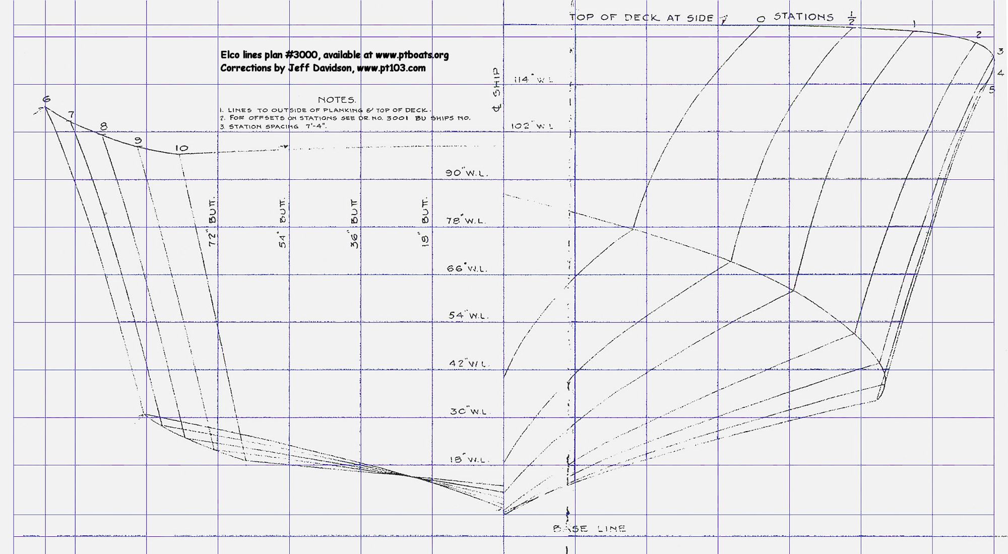
The following image shows hull sections located at the stations. It is derived from the Elco lines drawing 3000, available at http://www.ptboats.org/. Stations are evenly spaced 88" divisions along the LWL (length on water line, not the same as the painted W.L.). The LWL is 73' 4" (880") and goes from station 0 (68" aft of foremost point) to station 10 (948" aft of foremost point) with st 1/2 added between st 0 and st 1. I have straightened it the best that I could. The blue lines were added as guides for straightening. A larger version is Here.

Deck Camber Layout
Deck camber is 4.5" in 21' according to Elco drawing 3086, Type Sections, and Deck Framing drawings. The sheer varied slightly to match the designed sheer line. The radius works out to be 1766.25". See also the Specs page.

Hull Fittings
I have yet to research all of the different fittings on the hull itself but others have worked on it. Dick Washichek, the force behind The PT Boat Forum, made a nice graphic labeling some of the hull fittings which can be seen here: http://www.ptboatforum.com/cgi-bin/MB2/netboardr.cgi?fid=102&cid=101&tid=3099&sc=20&pg=1&x=0.
The best freely available reference for hull fittings is the Elco Parts Catalog which can be downloaded from this page: http://www.ptboatforum.com/PT_Boat_Documents.html. Diagrams and images of the fittings can be found within.
A discussion on hull grounding fittings can be found here: http://www.ptboatforum.com/cgi-bin/MB2/netboardr.cgi?fid=102&cid=101&tid=3946&pg=1&sc=20&x=0.
Daniele Klay sent me this, the results of his Elco drawing research into the self bailer outlets. Thanks Daniele! Check out his 1/16th scale build here: http://www.ptboat195.blogspot.com/.
Foreword : The bailer piping is noted on the drawings as applicable for PT 103-196 and 314-367. On PT 103-138 the outlets had to clear the grounding strip, so the offset from centerline should be at least 12". Also placements scaled from the General Arrangement views all fall in this range, only exception is at frame 28, where the offset scales at 14 1/2". So I think keeping a bit more than 12", say 12 3/8" for all outlets except at frame 28 should be reasonable.
Summing up:
Frame 21: 6 3/4" fwd, 12 3/8" to port. on the starboard side overboard discharge 1 3/4" fwd, 21 5/8"above chine line (no scoop, only through hull fitting).
Frame 28: 5 5/8" fwd, 14 1/2" to starboard.
Frame 39: 7 7/8" fwd. 12 3/8" to port.
Frame 47: 1 1/2" aft, 12 3/8" to port, on the port side overboard discharge 4 1/2" aft, 44 3/4" below deck line.
Frame 61: 4 1/2" fwd, 12 3/8" both sides.
Transom: 6 3/4" fwd of transom edge(minimum distance in order to clear the 3" binding angle), 12 3/8" to port.
NOTE all of this is subject to error, the General Arrangement drawing is inconsistent in plan/side view, no "real" drawing found yet.
|
Elco PT 103 Class Hull Numbers and Production Order
|
|
103-196
|
3355-3448
|
|
314-367
|
3449-3502
|
|
372-383
|
3503-3514
|
|
546-563
|
3515-3532
|
|
486-545
|
3533-3592
|
|
731-760
|
3593-3622
|
|
565-624
|
3623-3682
|
|
Elco 80' PT Boat Deck Beam Table
|
|
10 - 12 - 14 - 16 - 18 - 20
|
7/8" (.875")
|
1 3/8"
|
Oak
|
|
30 - 31 - 38 - 40 - 49 - 50 - 53 - 54 - 57 - 59 - 63 - 67
|
1 3/8" (1.375")
|
6"
|
Mahogany
|
|
64 - 66 - 68
|
7/8" (.875")
|
3"
|
Mahogany
|
|
All others
|
1 1/8" (1.125")
|
6"
|
Mahogany
|
Changes:
PT 486-545, 731-760, : Frames 10 - 12 - 14 - 16 - 18 - 20 molded changed to 3", material to mahogany.
PT 565-624: Same as above except frame 16 sided changed to 1 1/8" (1.125")", molded changed to 6".
Notes:
PT 139 and on drawings state regular, light, (and "intermediate" on the early drawings) deck beams.
center over side frames, heavy beams have after face flush with after face of frames.
Information is based on Elco deck framing drawings.
|
|
Elco 80' PT Boat Deck Construction Table
|
|
103-108
|
Mahogany planking, 2 layers
laid fore and aft
|
Inner layer 5/16", outer layer 3/8"
|
109-196, 314-367, 372-383, 487-497,
546-563, 731-760
|
Mahogany planking, 2 layers
laid fore and aft
|
Inner layer 3/8", outer layer 5/16"
|
|
486, 498-545, 565-624
|
Plywood
|
9/16"
|
Notes:
Coaming sits on lower layer of planking on plank decked boats.
Coaming sits on top of plywood on plywood decked boats.
Planked boats have a layer of marine glued airplane fabric between layers.
Information is based on Elco type section drawings.
|
|
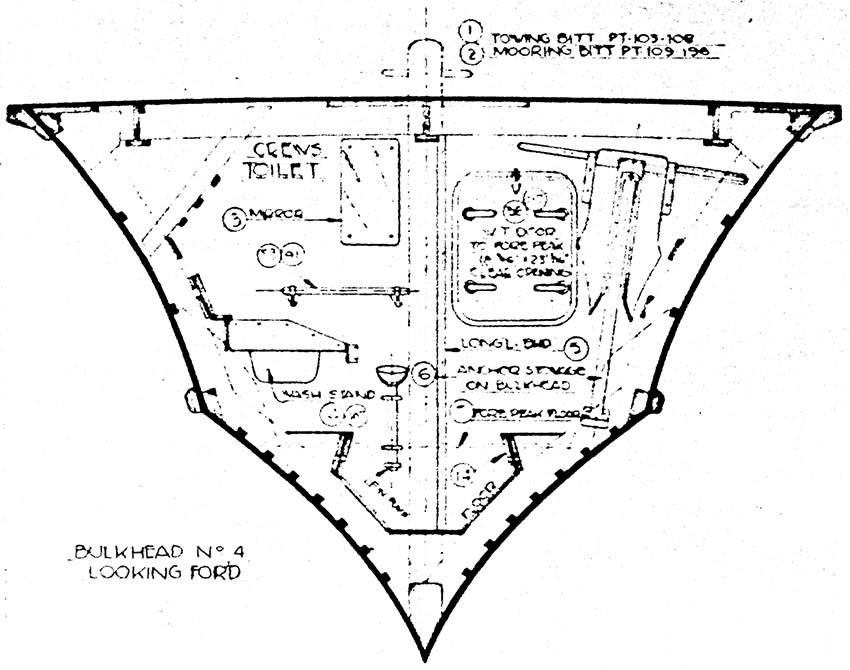
Frame Sections, 1942 Elco 80' Patrol Torpedo (PT) Boat
|
|
General Notes:
Section labels are from Elco Cabin Arrangement drawing 3008.
|
|
Forepeak
|
0 to 77"
From frames 0 to 4
|
6' - 5", 6.417', 77"
|
1 frame at 29":
0 to 1
3 frames at 16":
1 to 2 through 4
|
|
Crews Toilet
|
77" to 155"
From frames 4 to 9
|
6' - 6", 6.5', 78"
|
4 frames at 16":
4 to 5 through 8
1 frame at 14":
8 to 9
|
|
Crews Quarters
|
155" to 311"
From frames 9 to 21
|
13' - 0", 13', 156"
|
6 frames at 14":
9 to 10 through 15
6 frames at 12":
15 to 16 through 21
|
|
Officers Quarters
|
311" to 534.5"
From frames 21 to 39
|
18' - 7.5", 18.625', 223.5"
|
12 frames at 12":
21 to 22 through 33
5 frames at 13.5":
33 to 34 through 38
1 frame at 12":
38 to 39
|
Tank Compartment
Crews Day Room Over
|
534.5" to 650"
From frames 39 to 47
|
9' - 7.5", 9.625', 115.5"
|
1 frame at 12":
39 to 40
6 frames at 15":
40 to 41 through 46
1 frame at 13.5":
46 to 47
|
|
Engine Compartment
|
650" to 854"
From frames 47 to 61
|
17' - 0", 17', 204"
|
1 frame at 10":
47 to 48
11 frames at 16":
48 to 49 through 59
2 frames at 9":
59 to 60, 61
|
|
Rudder Compartment
|
854" to 960"
From frames 61 to 69
|
8' - 10", 8.833', 106"
|
1 frame at 9":
61 to 62
7 frames at 12":
62 to 63 through 69
|
|
Frame Spacing, 1942 Elco 80' PT Boat
|
|
General Notes:
Measurements are to aft face of frames per drawings.
Frame 69 is a partial frame that intersects the transom.
** = watertight bulkheads.
|
|
1
|
2
|
3
|
4 **
|
5
|
6
|
7
|
8
|
9 **
|
10
|
|
29"
|
45"
|
61"
|
77"
|
93"
|
109"
|
125"
|
141"
|
155"
|
169"
|
|
|
|
|
11
|
12
|
13
|
14
|
15
|
16
|
17
|
18
|
19
|
20
|
|
|
183"
|
197"
|
211"
|
225"
|
239"
|
251"
|
263"
|
275"
|
287"
|
299"
|
|
|
|
|
21 **
|
22
|
23
|
24
|
25
|
26
|
27
|
28 **
|
29
|
30
|
|
|
311"
|
323"
|
335"
|
347"
|
359"
|
371"
|
383"
|
395"
|
407"
|
419"
|
|
|
|
|
31
|
32
|
33 **
|
34
|
35
|
36
|
37
|
38
|
39 **
|
40
|
|
|
431"
|
443"
|
455"
|
468.5"
|
482"
|
495.5"
|
509"
|
522.5"
|
534.5"
|
546.5"
|
|
|
|
|
41
|
42
|
43
|
44
|
45
|
46
|
47 **
|
48
|
49
|
50
|
|
|
561.5"
|
576.5"
|
591.5"
|
606.5"
|
621.5"
|
636.5"
|
650"
|
660"
|
676"
|
692"
|
|
|
|
|
51
|
52
|
53
|
54
|
55
|
56
|
57
|
58
|
59
|
60
|
|
|
708"
|
724"
|
740"
|
756"
|
772"
|
788"
|
804"
|
820"
|
836"
|
845"
|
|
|
|
|
61 **
|
62
|
63
|
64
|
65
|
66
|
67
|
68
|
69
|
|
|
854"
|
863"
|
875"
|
887"
|
899"
|
911"
|
923"
|
935"
|
947"
|
|

